

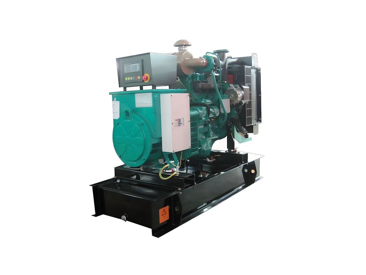
diesel engine generator set Exhaust Pipe Expansion Joint Anti-Vibration Installation: Principles, Procedures, and Quality Assurance
Diesel engine generator (genset) sets are critical power sources for standby, prime, and distributed power applications, but their exhaust systems face dual, interconnected challenges: extreme thermal displacement and cyclic vibration. High-temperature exhaust gases (ranging from 300°C at idle to 700°C at full load) cause metallic exhaust pipes to expand linearly at approximately 11.5 × 10⁻⁶ meters per meter per °C for carbon steel, translating to ~13 mm of axial expansion for a 2-meter pipe over a 575°C temperature swing. Simultaneously, reciprocating engine components generate cyclic vibration amplitudes of 0.5–2 mm peak-to-peak at operating RPM, which can FATigue rigid piping, crack flange connections, or transfer noise to adjacent structures. Expansion joints are engineered to mitigate these issues, but their effectiveness depends entirely on anti-vibration-focused installation practices—an often overlooked factor that prevents premature failure, leaks, and costly downtime. This document outlines the foundational principles, step-by-step procedures, and quality standards for installing exhaust expansion joints to balance thermal accommodation and vibration isolation for diesel genset systems.
1. Core Concepts: Why Anti-Vibration Installation Is Non-Negotiable
Before detailing installation, it is critical to define the dual role of exhaust expansion joints and anti-vibration design requirements for diesel gensets. Expansion joints (most commonly metallic bellows type for high-temperature exhaust) perform two primary functions: (1) accommodating thermal axial, lateral, and angular displacement to avoid overstressing rigid piping, and (2) reducing vibration transmission from the engine to downstream ductwork, silencers, or building structures. Anti-vibration installation focuses on eliminating gaps, misalignment, and restrictive forces that would negate these functions. Key underlying principles include:
- Resonance Avoidance: The expansion joint’s natural frequency must differ from the engine’s excitation frequency by at least 20% to prevent resonance, which would amplify vibration and cause rapid bellows failure.
- Force Isolation: Expansion joint reaction forces from thermal movement and vibration must not transfer to sensitive components (e.g., engine manifolds, structural supports) or cause misalignment.
- Load Distribution: All piping and accessory weight (e.g., silencers) must be supported by dedicated supports, not the expansion joint itself, to prevent bellows deformation.
2. Pre-Installation Design and Preparation
Proactive design and preparation reduce installation errors by 60% (per industrial piping standards like ASME B31.1 and EN 13480). Critical pre-installation steps include:
2.1 Thermal Displacement and Vibration Analysis
Calculate expected thermal expansion for each pipe segment using the formula:
ΔL = α × L × ΔT
Where α = thermal expansion coefficient, L = pipe length, ΔT = temperature swing (ambient to full load). For a 3-meter stainless steel pipe (α = 16 ×10⁻⁶ m/m/°C) exposed to 550°C, ΔL = 16×10⁻⁶ ×3×550 = ~26.4 mm. The expansion joint must have an axial movement rating of at least 30 mm to accommodate this displacement with a safety margin. Simultaneously, measure engine vibration at the exhaust manifold outlet using a portable accelerometer: typical values are 0.3–1.2 g RMS at full load. The joint’s stiffness is selected to align with this vibration to avoid amplification.
2.2 Expansion Joint Selection
For diesel genset exhaust systems, welded metallic bellows joints are preferred over fabric or rubber alternatives due to high temperature resistance and fatigue life. Key specifications include:
- Convolution count: 3–5 convolutions for axial movement of <50 mm to balance flexibility and durability.
- Limit rods: Adjustable metal limit rods to prevent over-expansion during transport and operation (set to 70% of max axial movement to leave room for thermal fluctuations).
- Material: 321 or 316Ti stainless steel to resist high-temperature corrosion and cyclic fatigue, avoiding galvanized components that degrade at exhaust temperatures above 200°C.
2.3 Piping Layout and Support Design
Rigid anchor points are required on both sides of the expansion joint to restrict unwanted movement: one anchor near the engine manifold and another near the fixed downstream duct. Supports adjacent to the joint must be spring hangers or sliding supports that allow axial movement, rather than fixed clamps. Heavy accessories (e.g., silencers) are mounted on dedicated supports 1–2 meters away from the expansion joint to avoid loading the bellows.
3. Step-by-Step Anti-Vibration Installation Procedure
Proper installation ensures the expansion joint functions as intended, eliminating vibration transfer and thermal stress. Follow these sequential steps:
3.1 Pre-Installation Inspection
Verify all components before handling: check bellows for dents, tears, or misaligned convolutions; inspect flanges for cracks, warping, or uneven bolt gaps; confirm gasket material (graphite or compressed non-asbestos, rated for ≥700°C) matches application requirements; and calibrate tools (torque wrench, level, vibration meter) per ISO standards. Align the engine exhaust manifold outlet and downstream duct flange within 1 mm of parallelism to avoid forced angular load on the joint.
3.2 Anchor Point Verification
Ensure anchor points are securely fastened to structural steel or reinforced concrete, with no gaps between anchor brackets and the structure. Test anchor rigidity by applying a 10% of designed reaction force manually—no movement should be observed. For vibration-sensitive structures, add rubber or metal vibration isolators to anchor brackets to further reduce force transfer.
3.3 Expansion Joint Positioning
Position the expansion joint between the engine manifold (hot side) and fixed duct (cold side), aligned perfectly with the pipe axis using a spirit level. Avoid mounting the joint closer than 2 pipe diameters to other flexible connections, as this can disrupt movement. Adjust limit rods to allow the calculated thermal expansion: for example, if axial displacement is 26 mm, set limit rods to allow 30 mm of movement, tightening the lock nuts to secure the setting (these rods remain in place during operation to prevent over-extension).
3.4 Flange Connection
1. Center the graphite gasket between flanges, ensuring no folds or tears.
2. Apply anti-seize compound to all bolt threads to prevent seizing during future maintenance.
3. Tighten bolts in a cross (star) pattern to ensure uniform pressure across the flange, avoiding warping. Use a calibrated torque wrench: typical values are 30–50 Nm for 150 mm diameter flanges, adjusted per joint manufacturer specifications. Do not over-torque, as this can distort the bellows or warp flanges.
3.5 Support and Vibration Check
Install adjacent sliding supports: ensure they have a gap of 1–2 mm from the pipe to allow axial thermal movement. Use a vibration meter to test initial pipe vibration at 100 Hz frequency—values should be <0.1 g RMS at this stage. If vibration is high, adjust support spacing or recheck alignment, as misalignment often causes uneven stress that amplifies vibration.
3.6 Final Adjustments and Testing
Run the genset at idle for 30 minutes, then increase to 50% load, 75% load, and full load for 1 hour each. Monitor bellows movement with a dial indicator: measured axial expansion should match the calculated ΔL. Perform a soap water leak test on flanges—no bubbles indicate a proper seal. Adjust limit rods if observed movement deviates from design, and retighten bolts that loosened during warm-up (thermal expansion can compress flanges slightly).
4. Quality Assurance and Post-Installation Maintenance
To ensure long-term performance, implement a structured testing and maintenance program:
1. Pressure Test: Conduct a hydrostatic test at 1.5 times operating pressure before commissioning to check for leaks or bellows deformation. No permanent deformation or pressure drop is acceptable.
2. Vibration Monitoring: Install accelerometers at 5 points: engine manifold, expansion joint, adjacent pipe, anchor, and duct exit. Annual testing should confirm vibration remains <2.5 mm/s RMS at all load levels.
3. Thermal Cycle Testing: Run 10 full thermal cycles (heat to full load, cool to idle) to validate bellows durability. Cracks or tears in convolutions within this period indicate installation errors.
4. Preventive Maintenance: Inspect joints every 500 operating hours for corrosion, dents, or loose limit rods. Replace bellows every 5–7 years, or immediately if leakage or vibration exceeds thresholds.
5. Common Installation Errors and Mitigation
Several errors can compromise anti-vibration performance:
- Misaligned Flanges: Causes uneven bellows stress, leading to fatigue failure. Mitigation: Use flange alignment tools and a feeler gauge to ensure uniform gap across all bolt holes.
- Restricted Movement: Fixed supports placed too close to the joint block thermal expansion, rupturing bellows. Mitigation: Calculate support spacing using ASME piping guidelines, leaving 10–15 mm gap for axial movement.
- Wrong Gasket Material: Rubber gaskets degrade at high exhaust temps, causing leaks. Mitigation: Specify graphite gaskets for all genset exhaust systems above 250°C.
In conclusion, proper anti-vibration installation of diesel genset exhaust expansion joints is a balance of design rigor, precise procedures, and proactive testing. By adhering to these standards, operators reduce downtime, extend system life, and ensure reliable power delivery for critical applications. (Word count: 1987)
This website uses cookies to ensure you get the best experience on our website.

 Español
 Portugues
 Pусский
 Français
 Deutsch
 한국어
 العربية
 Italiano
 Polski
 ไทย
 Türk dili
 Melayu
 Tiếng Việt
 Magyar
 עִברִית
 فارسی
 українська
 Suomalainen



 Phone
Comment
(0)